We produce custom springs and wireforms. We do not stock standard parts.
We produce custom springs and wireforms. We do not stock standard parts.

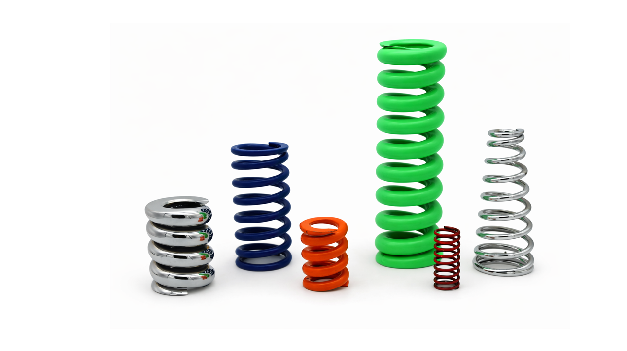


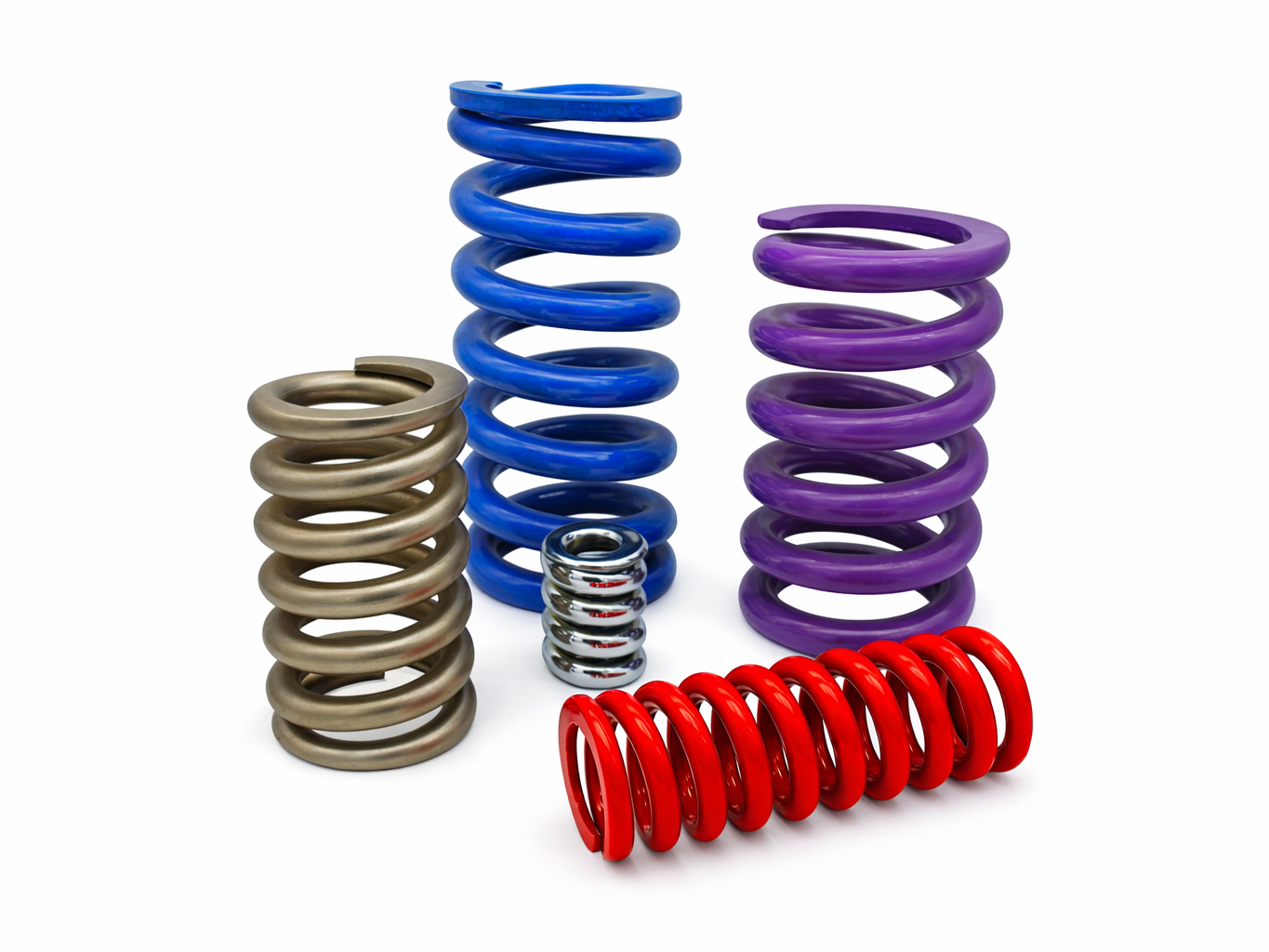
Compression springs are a type of wire spring engineered to resist compressive forces or store energy when pushed. Commonly used in everything from industrial equipment and motors to household appliances and medical devices, these springs compress under a load applied to their ends and return to their original shape when the force is released. This push-back action makes them essential in thousands of mechanical applications requiring durability, reliability, and consistent performance.
Typically manufactured as cylindrical helical coils made from round wire, compression springs can also be customized into conical, barrel-shaped, oval, or hourglass forms to suit specific design needs. The wire itself may be round, square, or rectangular, depending on the application. As one of the most widely used spring types, compression springs are found across a wide range of industries, including automotive, aerospace, electrical switchgear, military and defense, medical devices, consumer electronics, power generation, industrial machinery, firearms (such as custom gun and firing pin springs), and more.
Compression springs are essential components across a wide range of industries that demand durability, precision, and performance under load. At Ace Wire Spring & Form Co., Inc., we manufacture custom compression springs for engineers, designers, and purchasing agents who require reliable spring solutions built to exact specifications.
Our springs are proudly made in Pittsburgh, Pennsylvania and are used in the following industries:
Medical Devices – IV bag hooks, infusion pumps, and diagnostic equipment
Military and Defense – Firing pin springs, weapon systems, magazine springs, and tactical gear
Electrical Power and Switchgear – Circuit breakers, high-voltage switchgear, and insulation devices
Industrial Equipment – Machinery, actuators, clamping systems, and vibration dampening
Consumer Products – Appliances, tools, furniture, and electronics
Agricultural and Lawncare Equipment – Riding mowers, zero-turn mowers, and engine parts
Rail and Mass Transit – Coupling mechanisms, vibration control, and seating components
No matter the industry, Ace Wire Spring delivers high-performance compression springs that meet demanding requirements for strength, fatigue life, and consistency. Whether you need a custom prototype or full-scale production, we support you every step of the way with engineering assistance, fast turnaround times, and reliable delivery.
Take a moment to explore the variety of additional services Ace Wire Spring & Form Co. Inc., can perform on any type of spring or wire form to enhance performance and durability. From heat treatment, deburring, and painting to many more offerings, our secondary services are designed to meet your specific needs. Please include the secondary services you would like to add in the comment section of your request for quote, and our engineers will return an accurate and timely quotation with the added services. Visit our Secondary Services Page to learn more.
To review springs and wire form finishes such as e-coating, zinc plating, passivation, and many more, visit Wire Size and Material Range Page.
At Ace Wire Spring & Form Co., we provide flexible and reliable solutions to meet your manufacturing needs. Our expertise ensures precision, quality, and efficiency from prototype to production. For more details on these value-added services, visit our Custom vs. Stock Springs Page.

Compression Springs are open-coil helical springs that offers resistance to a compressive force applied axially. Helical compression springs are used to resist applied compression forces or to store energy in a push mode. Compression springs have the most common configuration and are most commonly used in automotive, aerospace and consumer applications. Most compression springs are a straight cylindrical spring made of round wire. Ace Wire Spring & Form, a manufacturer of compression springs produces a variety of compression types, shapes, and specific specifications. Click here for compression springs specifications.
Compression springs from a manufacturer come in a variety of types including: Conical Compression, Barrel, Hourglass and Cylindrical shapes and may have various spacing or no spacing at all between coils.
Wire Selection: rectangular, round, square or special-section. Round being the most adaptable.
Compression Spring Mandatory Specification: the functional design characteristics.
Compression Spring Secondary Specification: the secondary characteristics, which is useful for reference and should be considered advisory data.
Dimensional Limits: governed by the space allotted with regard to allowable solid height and outside and inside diameters.
Spring Stress Level: determined by the dimensional limits together with the load and deflection requirements. Our compression springs are stress-relieved to remove residual bending stresses produced by the coiling operation.

For Compression Springs – Rate which is the change in load per unit deflection, may be determined by the following procedure:
The solid height of compression springs is defined as the length of the spring when under sufficient load to bring all coils into contact with the adjacent coils and additional load causes not further deflection. Solid height should be specified by the user as a maximum, with the actual number of coils in the spring to be determined by the spring manufacturer. As square or rectangular wire is coiled, the wire cross-section deforms slightly into a keystone or trapezoidal shape, which increased the solid height considerably. The dimensional change is a function of the spring index and the thickness of the material.
This video shows how Compression Springs are manufactured.
For more information about compression springs or to talk to one of our experts call 1-800-828-3353.
ACE specializes in custom precision springs and wire forms, offering a distinct advantage by utilizing the most advanced spring design software. ACE validates each existing and new design, notifying the customer with our recommendations.


"Where it’s always SPRINGTIME!"
Copyright © Ace WIre Spring & Form Company, Inc. All Rights Reserved. Pittsburgh Website Design by Higher Images.


